Sunday, June 28, 2015

Session expired. Try to relogin. Client received SOAP Fault from server


I was trying to call an external web service in my project.

Recently the external web service got changed and they gave me a new url

I replace the new url with old url and tried to test my interface and i was getting below error

Unable to invoke endpoint URI "http://abasadasdasdasdasdasd" successfully due to: java.lang.RuntimeException: oracle.j2ee.ws.saaj.soap.SOAPVersionMismatchException: Mime Header Content-Type: text/xml requires SOAP envelope namespace: http://schemas.xmlsoap.org/soap/envelope/


The reason for this issue is that the WSDL content has changed in the process, however the end point URL is same.

This kind of issue mainly occurs in Siebel or magento services where in we have a local copy of WSDL.

In order to resolve the issue.

download the latest WSDL file from the URL

Replace it with the existing content of WSDL in Jdeveloper or in MDS.

Redeploy the process and you should be able to resolve this issue.


ConnectionFactory property platformClassName was set to org.eclipse.persistence.platform.database.oracle.Oracle10Platform but the database you are connecting to is Microsoft SQL Server.


I create a connection to MS SQL server in weblogic admin console and tried to test one of my process and i go the error below

Exception occured when binding was invoked. Exception occured during invocation of JCA binding: "JCA Binding execute of Reference operation 'write' failed due to: DBWriteInteractionSpec Execute Failed Exception. write failed. Descriptor name: [WriteToDD.InterfaceErrors]. Caused by weblogic.jdbc.sqlserverbase.ddc: [FMWGEN][SQLServer JDBC Driver][SQLServer]String or binary data would be truncated.. Please see the logs for the full DBAdapter logging output prior to this exception. ConnectionFactory property platformClassName was set to org.eclipse.persistence.platform.database.oracle.Oracle10Platform but the database you are connecting to is Microsoft SQL Server. Please validate your platformClassName setting. This mismatch can cause the adapter to trigger runtime exceptions or execute SQL that is invalid for the database you are connected to. This exception is considered not retriable, likely due to a modelling mistake. To classify it as retriable instead add property nonRetriableErrorCodes with value "-8152" to your deployment descriptor (i.e. weblogic-ra.xml). To auto retry a retriable fault set these composite.xml properties for this invoke: jca.retry.interval, jca.retry.count, and jca.retry.backoff. All properties are integers. ". The invoked JCA adapter raised a resource exception. Please examine the above error message carefully to determine a resolution.


The reason for this issue was that by default when we create a jndi it takes org.eclipse.persistence.platform.database.oracle.Oracle10Platform as platformClassName

I changed it to oracle.toplink.platform.database.SQLServerPlatform


AFter making the changes i updated the configuration plan and then i didn't get this issue.

Sunday, June 21, 2015

ORA-00604: error occurred at recursive SQL level 1


I was trying to call a DB procedure with complex (record/table types) parameters. When i tried to test the procedure i got the below error

ORA-00604: error occurred at recursive SQL level 1
ORA-06550: line 1, column 7:
PLS-00306: wrong number or types of arguments in call to 'SYNCRN'
ORA-06550: line 1, column 7:
PL/SQL: Statement ignored


This is a known issue as identified by oracle and a patch is already provided for DB. This issue is related to incompatible standard procedure with db version. Please refer to doc 1586704.1 for more details on this issue.

Thursday, June 18, 2015

Upgrade SOA Suite 10g project to SOA Suite 11g/12c


This document we will try to get details on how we can migrate the existing code in soa 10g to SOA11g/12c

First thing to understand is that there is no direct way to migrate SOA 10g code to SOA 12c.

You will have to redesign the code if you want to directly migrate the code.

However a hop approach is always recommended where in the 10g code are first migrate to SOA 11g and then to SOA 12c.

There are lot of things and points that must be taken care of while upgrading you project.

I have captured few of them in this exercise that will help to estimate the user how much complexity or time it will take for the whole migration.

Oracle Web cache as a load balancer


Oracle Web cache is a content management system. It works as a cache layer, as well as a load balancing layer for the underlying server. It is mainly used for load-balancing servers. Any website can be served by multiple origin server. Web cache balances the load among origin servers by determining the percentage of the available capacity, the weighted available capacity of each origin server.
The weighted available capacity is determined by the following formula:
(Capacity -Load)/Capacity
Where:
Capacity is the maximum number of concurrent connections that the origin server can accept.
Load is the number of connections currently in use.
If there are multiple origin servers and their available capacity is equal, the load balancing will be done based on round-robin algorithm.
To configure load balancing for a site, set the capacity of each origin server and create one site to server mapping that maps all the applicable origin servers to the site.
The diagram below represents a typical load-balancing pattern using Oracle Web cache. There are multiple host, which are hosting the application. The end user will pass the call to the Web cache which will redirect it to any of the host based on the routing algorithm defined for load balancing.


In order to achieve load balancing using Web cache, we will take two publicly available end-point URL. In this exercise, I will take oracle.com and ibm.com as the two end-point URLs. We will configure a front-end for the Web cache, which will be nothing but the front-end page for the client. We will configure this front-end page with the two end-point URLs we have defined. We will assign equal capacity to both the origin servers so that round-robin algorithm is followed, and we can call each of these end point on alternate calls. This is an example to depict the power of Web cache as a load balancer. However, in the actual context, Web cache is used for load balancing fusion applications, e.g., Service Oriented Architecture (SOA) server, OSB services, report server, etc.
Following are the steps that needs to be done in order to configure a load balancer. The assumption is that the Web cache set up is already done, please refer to the Appendix section for the installation details.
1. Access the Web cache page.
Login to the home page of Web cache using the following URL:
http://host:port
By default, the user will be ias_admin and password will be the one which you have used during installation.


Once you are logged in to Web cache you will get the following page.


Configure load balancing
Go to the following location.
(Windows) ORACLE_INSTANCE\\config\WebCache\\ webcache.xml
Locate the CACHE element at the last of the file.
Add the ROUTINGONLY=”YES” attribute to the CACHE element.


Save webcache.xml.
3. Restart Oracle Web Cache.
Use the following command:
opmnctl restartproc ias-component=component_name
This executable is found in the following directory:
(Windows) ORACLE_INSTANCE\bin


After restarting, if you will log in to the Web cache console, you will find that it is now configured for route only that appears at the top of the screen as shown below


Define Origin Server.
Go to the origin server and define two servers which you wanted to be load balanced.


Go to the site-to-server mapping and create a new mapping which will map the existing defined site to multiple origin server as shown below.


Submit and apply the changes and restart Web cache to take effect.


Validate configuration
Restart and now again check with the defined site and port.
In the first hit it, will redirect to the Oracle home page.

The second hit will redirect to the IBM home page.

As we have defined the capacity for both the servers to be equal, the load balancer is redirecting it in a round robin fashion.
In an ideal situation, all the managed servers in a cluster are defined in the origin server and they are load balanced by the Web cache layer


Wednesday, June 17, 2015

Oracle Service Bus as load balancer


OSB has a built-in support for load balancing as business services in OSB allows multiple end points to be added that can be load balanced using predefined load-balancing algorithm.
The load balancing will be achieved by creating two business services:
• Business Service A — This will be a real business service which will accept an input and will reply with some output.
• Business Service B — This will be a pass-through service which will not give any response.
A proxy service will be created later which will load balance between these two business services. Based on the load-balancing algorithm, one of the business service will be called. For e.g., if it is a round-robin algorithm — for the first invocation of proxy service, it will call Business Service A and for the subsequent invocation it will call the Business Service B.


As discussed earlier, we will create two business services first, then a proxy to call them in load-balancing algorithm. The assumption is that user has the basic knowledge of OSB.
1. Create Business Services
Log in to OSB console using the following URL:
http://host:port/sbconsole
Once you are logged in to OSB console, create an OSB session.


After the session is created, go to project explorer and create a new folder for your project.
The business service we are going to use in our implementation is following:
http://www.html2xml.nl/Services/Calculator/Version1/Calculator.asmx?WSDL
Create a Web Service Description Language (WSDL) resource in your project.
Specify it a unique name and paste the content of the WSDL mentioned in the high-level solution.


Save the changes for the WSDL and create a business service based on the above WSDL as shown below:


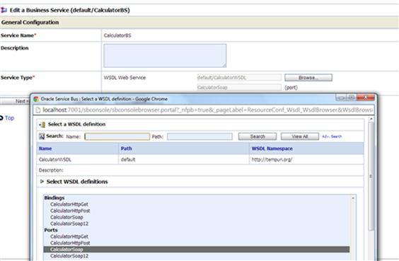
Select CalculatorSoap port and complete the wizard.


The actual end-point location of the calculator Web service gets added in the list.
It uses a round robin load-balancing algorithm by default.
2. Add service for load balancing
Click on add and you will find that one more address in added in the existing URLs list.


Now, here the second URL that we have added is not an actual Web service, it is a dummy end-point URL added by the wizard itself. (This is the second dummy service which we will use in this case to be load balanced.)
As per the current configuration, it says that we now have two end-point URL’s in the business service which are load balanced internally using a round-robin algorithm.
You can change the algorithm based on your requirement, keep the default format for testing.
Complete the wizard

Save the change and activate your OSB session.
3. Create Proxy Service
Create a wrapper OSB proxy service to call this business service.
Go to your project explorer.
Create a proxy service from the resource wizard and just call the business service you have created now.


Complete the configuration. Save the configuration and activate the changes.
This is the proxy service which will call the two business services in a load balancer.
4. Test the configuration
Test the proxy service.
Test the proxy service with the default input.
You will get two sets of output when two consecutive tests are performed.
One will fetch you a correct result and other will say the business service does not exist.
This happens because internally the two end-point URL’s specified in the business service are load balanced using round-robin algorithm, which means the services will be called on a round robin fashion, i.e., if first call fails (calling the dummy end point), the second call will succeed.
Below is the output for a consecutive call to the proxy service.


As discussed in the log balancing algorithm, the load balancer moves from one service to another as per the algorithm. In this scenario, it was round-robin algorithm, hence the proxy service first called the business service that is developed and then it called the dummy end point URL.

Tuesday, June 16, 2015

Mobile App in Jdeveloper

"

Dynamic partnerlink in OSB


Dynamic Partnerlink in OSB can be implemented in two ways.
1> URI override to achieve dynamic service invocation.
This sample is already provided by oracle and can be downloaded from the following link
http://java.net/projects/oracleservicebus1031/downloads/download/DYNAMIC-DISPATCH.zip
2> Dynamic routing based on input values.
When you do not know the service you need to invoke from the proxy service you are creating, you use dynamic routing. In this use case a scenario will be created where in, based on the input values business process will be invoked. Two business service will be created which will be writing data to two different folder. A proxy service will be created which will be exposed to client. This proxy service will be the entry point for the interface. Depending upon the input request from the proxy service one of the business service will be chosen at run time and the file will be written to the corresponding folder defined by business services. In order to choose the business service dynamically an XQuery file will be created which will contain the location of the business services. Based on input parameter the location of the business service will be retrieved from the XQuery file. This will be passed to a dynamic routing link which will route the request to the corresponding business service.

Create two business services which will write to two different folder location and name them as GoldClass and SilverClass.

Create two business Service to write file into a particular folder location. Here are the steps for one of the business process, the same steps can be followed to create other one too.
Create a business service of Any XML type


Make sure you already have created two folders named “GoldClass” and “SilverClass” where data file can be written to.
Choose file as protocol and add the GoldClass folder location as shown


Click on next and save the changes.


Follow the same steps and create one more business service for SilverClass.
Once completed you should be able to see the two business service in your folder.


Create an XML document for XQuery
Use the following xml document for the XQuery
Here logical name is the name which will come as input parameter from the client and the physical name is the name of the actual business service.
<routing>
<row>
<logical>Gold</logical>
<physical>default/GoldClass</physical>
</row>
<row>
<logical>Silver</logical>
<physical>default/SilverClass</physical>
</row>
</routing>

As you can see the physical location is nothing but the path of business service in OSB. Since we have created two business service GoldClass and SilverClass within Default folder the path to reach them will be default/GoldClass and default/SilverClass


Create an XQuery file and copy the contents


Create a proxy service


Keep the default properties and save the proxy service.
Save the Proxy service.
Edit the message flow.
Add a pipeline pair
Add a stage in request pipeline


Edit the Stage1
Add an assign activity and assign the XQuery to a temp variable. This is done so that later point of time it can be used


Retrieve the logical data from the input payload using the following XPath
$body/routing/row/logical
This assign activity will try to retrieve the logical location from the input parameter that will be passed from the proxy service.
Again use an assign activity and assign this value to another temp variable


Now use one more assign activity and this activity the actual physical location will be identified based on the logical input. Use the following routing code to retrieve the actual physical location and assign it to a temp variable. This code compares the logical identifier received from the proxy service and the logical identifier defined in XQuery file and output the corresponding physical location of the business service.
<ctx:route>
<ctx:service isProxy=’false'>
{$RouteTable/row[logical/text()=$logicalIdentifier]/physical/text()}
</ctx:service>
</ctx:route>


Save the output of this expression to a temp variable output.
This variable will now contain the actual location of the business service.
Save your process.
Go back to pipeline and add a route action


Add a dynamic routing and route it to the temp variable where you have retrieved the actual physical location of the business service. Since output is the variable where the actual location is saved we will use the same in dynamic routing.


Save the process and activate the changes.

Test the proxy service

Use following input


You will get the following invocation


Dynamic partnerlink in SOA


The dynamic partnerlink feature enables you to dynamically assign an endpoint reference to a partnerlink for use at runtime in BPEL versions 1.1 and 2.0. It is similar to switch activity in the sense that based on the input condition it evaluate the end point dynamically
In this implementation we will first try to understand how dynamic partnerlink can save the complexity and time for developer at design time. Let suppose there is a requirement to design process for which the end point is not fixed i.e. there are multiple end points that can be used. In an ideal scenario a developer will define multiple partnerlink and will write separate logic to use them. This will un necessarily complicate the code. This can be simplified using a single dynamic partnerlink. In order to achieve this we will first create three web services (end point URL) based on same wsdl. These will be a simple web services which will accept the input, will do some enhancement and will return it back to the calling service. Next is we will define another process where in we will define a dynamic partnerlink to call these end point url based on input. In order to achieve this a variable will be created based on ws-addressing Endpoint-reference (more detail on the implementation). This variable will serve as an input to the dynamic partnerlink for deciding on which web service has to be called. Based on the input this variable will be updated with the end point url of the predefined web services and the services will be called dynamically. In our typical use case we have defined 3 services which will be called based on the input values. If input is less than 5 call ServiceA, If it is between 5 and 10 call ServiceB otherwise call ServiceC. All these invocation will done through a single partnerlink in the calling process.

First of all define three business service.
Create three business service based on same input parameter and output parameter but may have different logic for implementation.

Let’s call them ServiceA, ServiceB and ServiceC.


Get the end point url for these three services as below
http://localhost:8001/soa-infra/services/default/ServiceA/servicea_client_ep?WSDL
http://localhost:8001/soa-infra/services/default/ServiceB/serviceb_client_ep?WSDL
http://localhost:8001/soa-infra/services/default/ServiceC/servicec_client_ep?WSDL
Now Create a WSDL which contain these services as shown below.


The important point to note is that all the services will be based on same binding and port that is all the services needs to have similar input and output format that is the message type will remain the same. As it appears all the services calls the actual end point url of the Services we have defined in the first step.
Create a synchronous BPEL process and drag and drop a web service in the external reference of the composite.
Define this web service based on the WSDL you have created now.
So once complete these steps your process will look like this.


The next step is to create a variable from ws-addressing XSD available in w3.
Import the schema from the following url in to your jdeveloper as ws-addressing.xsd
http://schemas.xmlsoap.org/ws/2003/03/addressing/


Create a variable based on the end point reference in the schema.


Now go to your BPEL process and assign following to the end point reference variable
<EndpointReference xmlns=”http://schemas.xmlsoap.org/ws/2003/03/addressing”>
<Address/>
<ServiceName/>
</EndpointReference>


Create one more variable EndPointUrl to store the end points of the services. The end point we will derive dynamically based on the input condition. Map this end point URL to the Address field in the EndPointReference.


Finally assign the end point reference variable to the partner link


Complete the process by invoking the partnerlink and assigning the input and output parameter. After completing all these steps your process will look like this.


Retrieve the end point url dynamically based on input parameter.
To achieve this put a switch activity just after the receive activity and define 3 conditions. This condition can be based on the real business logic. However for implementation to make easy lets define a simple condition
i.e. if input payload is less than 5 redirect it to Service A
If input payload is between 10 and 5 redirect it to ServiceB and
If input payload is greater than 10 redirect it to ServiceC
Once you defined the three conditions assign the end point url to the corresponding service to the variable “EndPointUrl”


Complete the assignment for all the three conditions and deploy your project to the server.

Test the Dynamic Partnerlink service.
To test the invocation of Service A pass an input value less than 5 so let’s pass 4 as input and test the result
Log in to em console.
Click on your process and click on test button


Specify input as 4


And test the service
Check the response


And check the Audit trail